Solar Powered Sensor with Supercapacitors and ESP32
Mon, Mar 16, 2020Motivation and ideas
I want to build a solar powered sensor that uses supercapacitors instead of batteries and can run for years without any intervention.
The full story is a little more complex:
Some years ago I stumbled accross the ESP8266 and ordered a couple of them and had quite fun playing around. I mainly explored the software side and the WLAN capabilities. At some point I ordered ESP32 microcontrollers and a couple of sensors and created a indoor temperature and humidity sensor with a small webserver that could display a reasonable amount of historic data. The BME280 from Bosch comes at a reasonable price with good precision. The Wemos LOLIN32 ESP32 development board has a low power consumtion in deep sleep mode.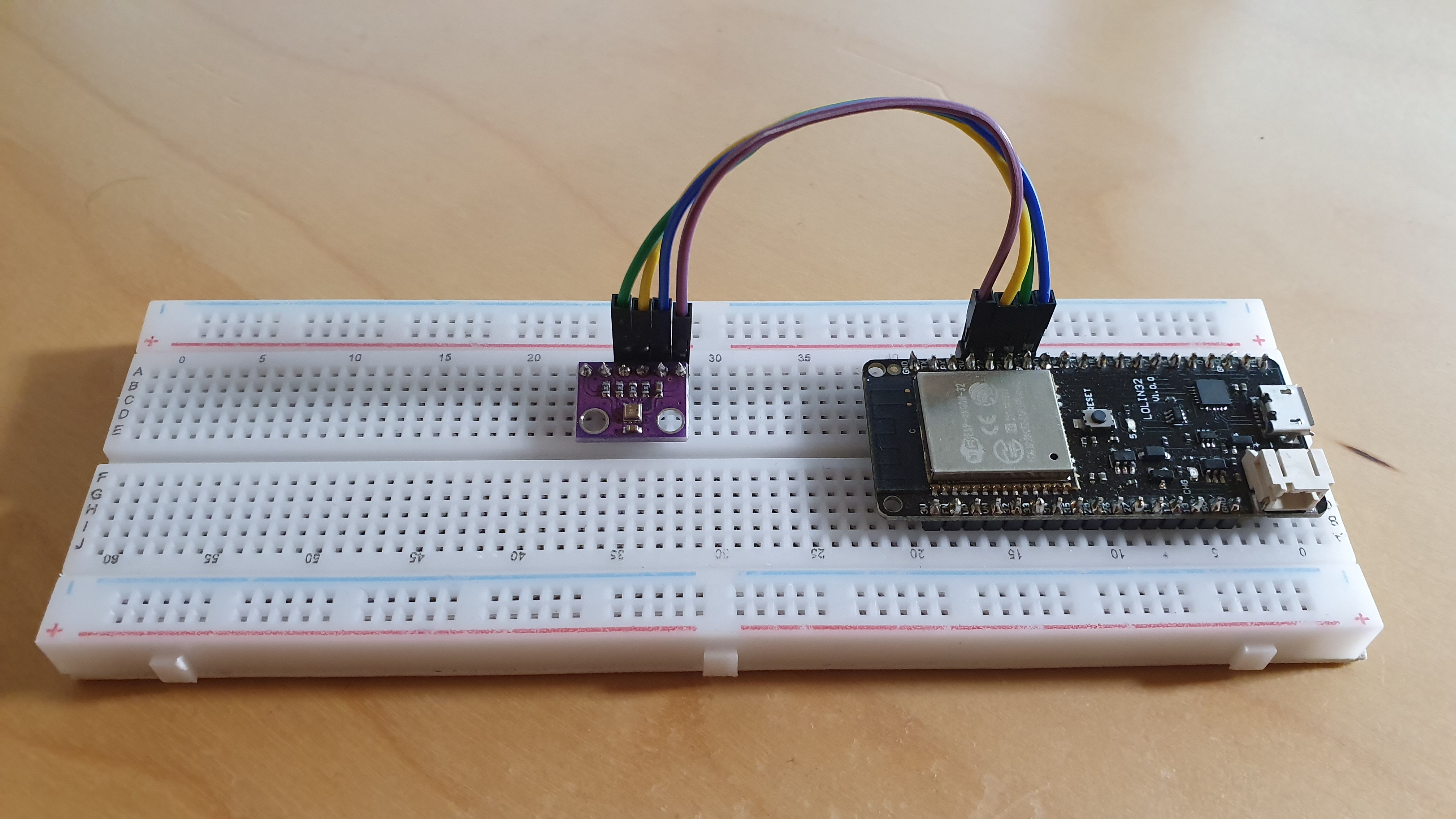
BME280 Temperature, Humidity and Pressure Sensor connected to an ESP32
Writing the software was “easy”. Things became hard when I wanted to put the sensor into a room with too few power socket. My development board has an USB connector and so I just connected it to a power bank, which quickly ran out of juice. I started looking into the power saving capabilities of the ESP32 and quickly hit a dead end: All power banks I own shut down shortly after the microcontroller goes into deep sleep mode. They all require a minimum load to stay on. I needed another way to power the sensor.
I started looking into various options:
- Battery powered
- Solar powered with a battery
- Solar powered with supercapacitors
Different sensor designs
Battery powered sensor
My ESP32 boards have a battery connector. I could have just bought a battery, use the deep sleep mode for power saving and a simple circuit to measure the battery voltage and report it together with the other sensor reading. It would have lasted a couple of months and I would than have to replace the batteries. I did not like the idea of recharging batteries.
Solar powered sensor with a battery
Although small solar cells would be able to charge the battery, I would have to replace the battery every few years. I did not try it but I did not like the idea either.
Solar powered sensor with supercapacitors
I really liked the idea to power everything with a combination of small solar panels and supercapacitors. Supercapacitors can store way less energy than a battery of the same size, but that’s ok because I only plan to send a couple of updates per day. I have some ideas to save energy that I haven’t seen implemented yet:
- Measure frequently and store the readings instead of sending them
- Send multiple reading at the same time to save power
- Send updates if readings out of the normal range are detected
- Use the voltage measurements to adjust the update frequency
Solved problems building the sensor
Properly power an ESP32 or similar microcontroller
If not properly powered a microcontroller like the ESP32 can be unstable. Sending data using WLAN requires a lot of power and can result in power fluctuations which cause the ESP32 to crash. For me this problem even occured when using a USB power supply.
The solution to the problem is to add one or more reasonable sized capacitors close to the pins supplying power to the ESP32. I ended up soldering two 470 µF capacitors directly accross 3.3V and GND. The two 470 µF capacitors soldered to 3.3V and GND help to prevent voltage fluctuations when sending data using WLAN. Without the capacitors the ESP32 was unstable.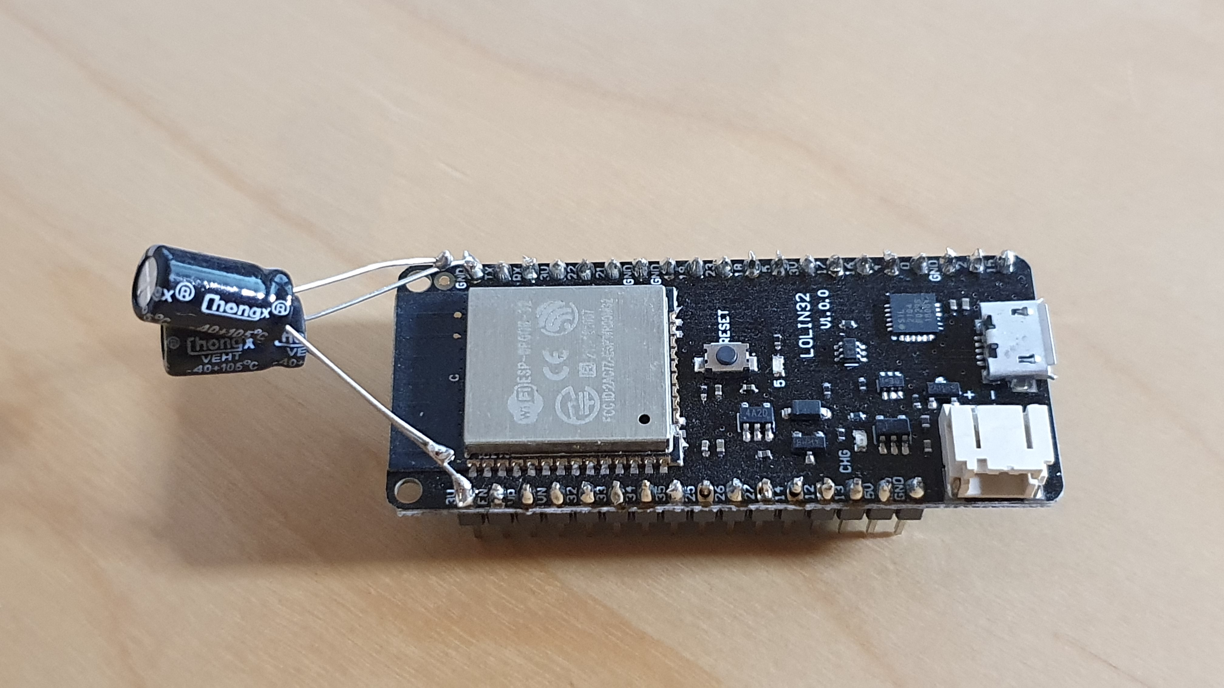
LOLIN32 ESP32 with two 470 µF capacitors
When researching this problem I found the excellent YouTube Channel of Andreas Spiess. In Video #0911 he investigates the problem and also presents the solution.
Charging supercapacitors with solar panels
When you charge a capacitor using a solar panel there are a number of problems that need to be addressed:
- Discharging of the capacitor through the solar panel
- Overcharging the capacitor
- Boosting small voltages
Prevent the capacitor from discharging through the solar panel
If you connect a capacitor directly to a solar panel the capacitor will be charged when there is light, but when it becomes dark the opposite will happen and the capacitor will be discharged into the solarpanel. To prevent this you can add a diode. The diode will allow the capacitor to charge at the cost of a voltage drop but prevent it to discharge into the solar panel. The diode allows the current to flow from the solar panel to the capacitor but prevents it from flowing back.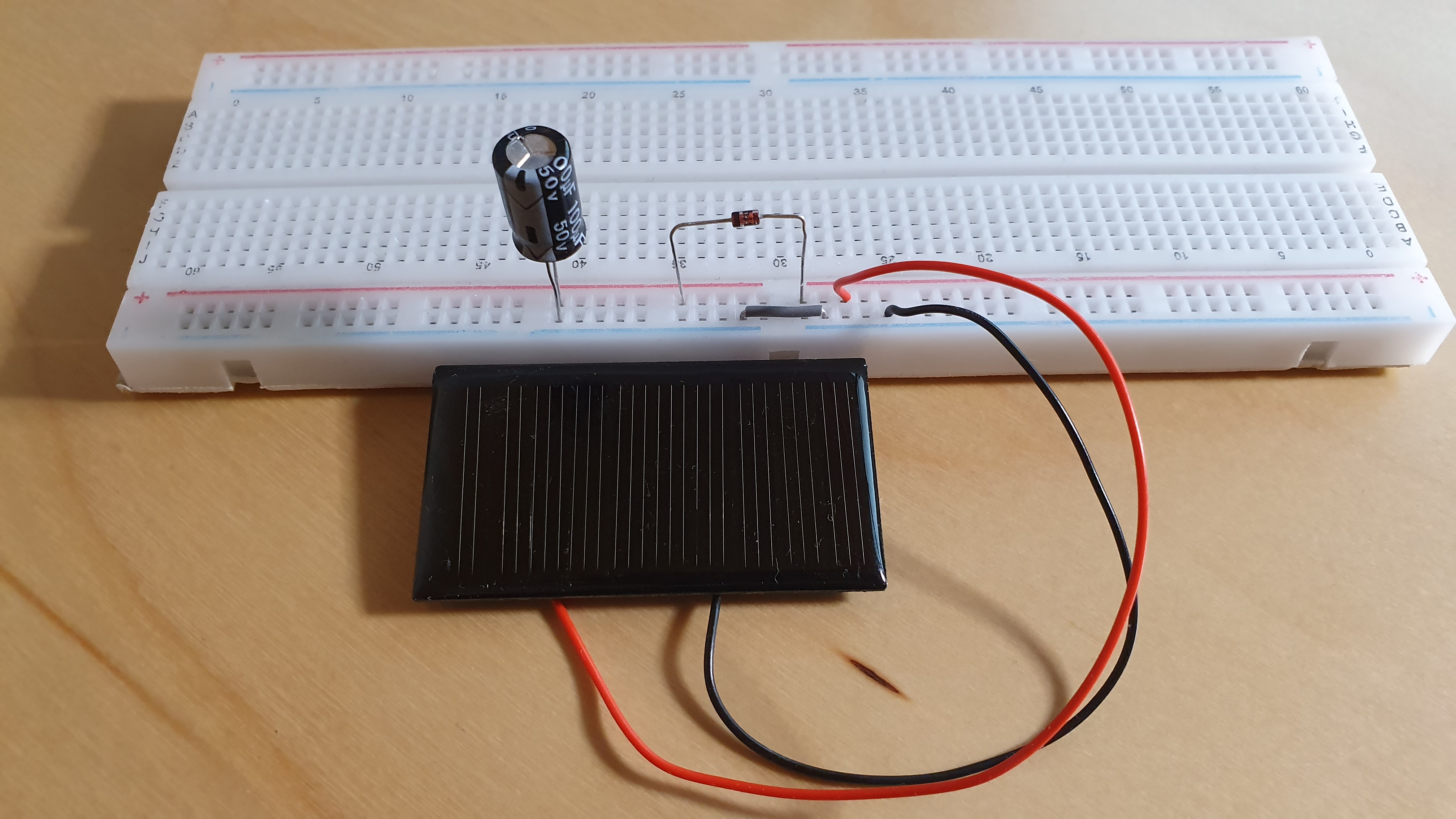
Solar panel connected to a capacitor through a diode
Protect the capacitor against overcharging
Capacitors are rated for a specific voltage. Most supercapacitors are rated for 2.7 V. Charging them higher will damage them. With a TL431, which is a programmeble reference, there is a cheap way to protect the capacitor from overcharging. The reference of the TL431 is connected directly to the cathode (+) and therefore limits the charge of the capacitor to 2.5 V.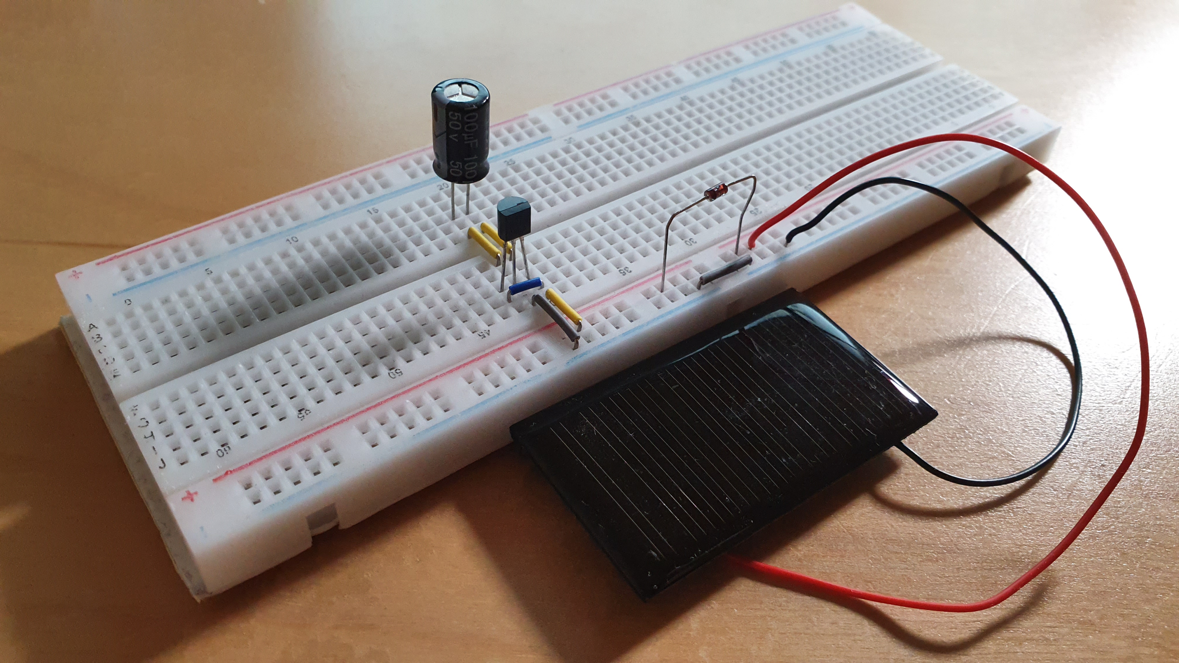
Capacitor protected with cheap TL431
In Video #1392 of his YouTube channel, Andreas Spiess points out this cheap solution.
Measure capacity and loss of supercapacitors with ESP32
If you buy cheap supercapacitors you might want to test them to assure that they are of good quality. For me this means:
- The Capacity should be within an acceptable tolerance of the advertised value
- The Capacitors should hold the charge for a reasonable amount of time
Normal capacitors could easily be tested with a multimeter or a cheap parts tester. This however does not work for supercapacitors with an capacity of 5, 10 or 20 Fahrad. I wanted an cheap solution to test my capacitors and found one:
Measure Capacitance using RC Time Constants
Wikipedia states:
The RC time constant, also called tau (𝜏), the time constant (in seconds) of an RC circuit, is equal to the product of the circuit resistance (in ohms) and the circuit capacitance (in farads), i.e.
𝜏 = RCIt is the time required to charge the capacitor, through the resistor, from an initial charge voltage of zero to approximately 63.2% of the value of an applied DC voltage
If we know the resistor and measure the time to charge the capacitor to 63.2 % of the applied voltage we can calculate the capacitance using: C = 𝜏 / R
Circuit to measure the capacitance
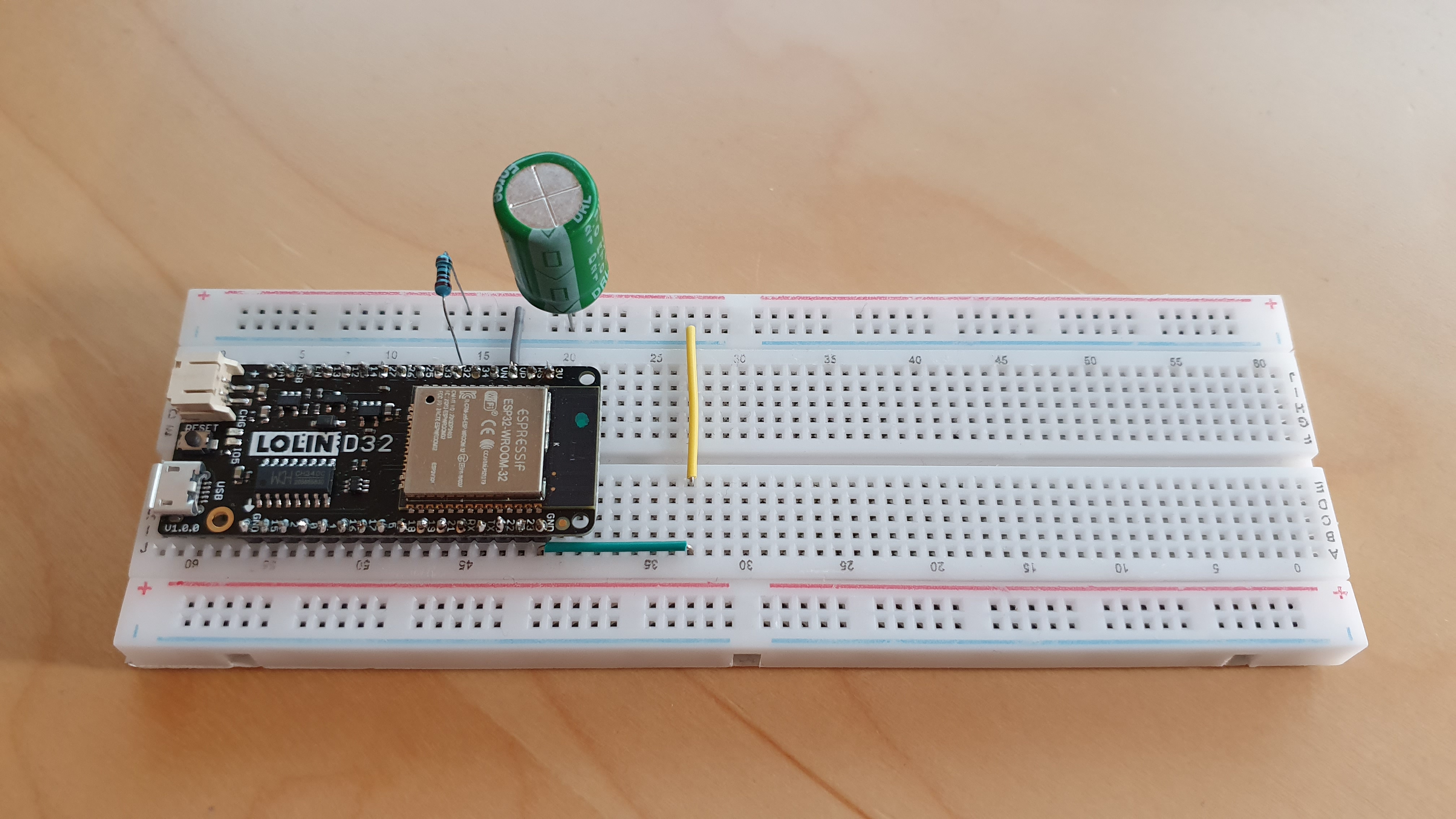
ESP32 capacitance meter
The supercapacitor is charged using a known resistor (e.g. 200 Ω) using the 3.3 V output voltage of the ESP32 to up to 63.2 %. The voltage is constantly measured using one of the ADC pins.
Arduino sketch to measure capacitance and loss using an ESP32 and a resistor
// Pins
#define analogPin 36 // analog pin for measuring capacitor voltage - connected to the anode (+) of the capacitor
#define chargePin 32 // pin to charge the capacitor - connected to the charging resistor

// Resistor
#define resistorValue 199.9F // resistor value in Ohm; F formatter tells the compliler it's a floating point value

// Voltage
float analogReading = 0;
float chargedVoltage = 0;

// Times
unsigned long progressUptdateInterval = 10; // Output progress every x seconds
unsigned long lossTestDuration = 60 * 60;   // Test time for loss is seconds

unsigned long startTime;
unsigned long capacityStartTime;
unsigned long lossStartTime;

unsigned long lastProgressUptdateTime;
unsigned long elapsedTime;

// Capacitor
float capacity = 0; // floating point variable to preserve precision, make calculations
float output;       // floating point variable for output after calculations
float loss = 0;

void setup()
{
  // Initialize serial transmission for debugging
  Serial.begin(115200);
  Serial.println("");

  // Start Timer
  startTime = millis();

  // Set ADC settings
  // https://www.youtube.com/watch?v=RlKMJknsNpo&t=145s
  analogReadResolution(12);       // 12 bits
  analogSetAttenuation(ADC_11db); // for all pins (11db = 0-3.3v)
  analogSetCycles(255);           // default is 8, range 1-255
  analogSetSamples(1);            // default is 1
  analogSetClockDiv(1);           // default is 1, range 1-255

  // Discharge the capacitor
  discharge();

  // Test capacitor
  Serial.println("=== CAPACITY TEST==========");

  // Prepare Pins
  pinMode(chargePin, OUTPUT);    // set chargePin to output
  digitalWrite(chargePin, HIGH); // set chargePin HIGH and capacitor charging

  // Start Timer
  capacityStartTime = millis();

  // Measure charging
  analogReading = measure();
  while (analogReading < 2588)
  { // 2588 is 63.2% of 4095, which corresponds to full-scale voltage
    analogReading = measure();
    if (lastProgressUptdateTime + progressUptdateInterval * 1000 < millis())
    {
      Serial.print("Capacity test\t");
      Serial.print(analogReading * (100.0 / 2588.0), 1);
      Serial.println(" %");
      lastProgressUptdateTime = millis();
    }
  }
  // stop charging
  pinMode(chargePin, INPUT);

  // Calculate elapsed time
  elapsedTime = millis() - capacityStartTime; // milliseconds

  // Calculate Capacity
  capacity = ((double)elapsedTime / resistorValue) * (1000000); // in nF
  delay(2000);

  // Test loss
  Serial.println("=== LOSS TEST =============");

  lossStartTime = millis();

  chargedVoltage = measure();

  while (millis() < lossStartTime + 1000 * lossTestDuration)
  {
    if (lastProgressUptdateTime + progressUptdateInterval * 1000 < millis())
    {
      analogReading = measure();
      loss = (1 - (analogReading / chargedVoltage)) * 100;
      Serial.print("Loss test\t");
      Serial.print(((millis() - lossStartTime) / (float)(1000 * lossTestDuration)) * 100, 1);
      //Serial.print(analogReading * (100.0 / 4095.0), 2);
      Serial.println(" %");
      lastProgressUptdateTime = millis();
    }
  }

  discharge();

  // Calculate elapsed time
  elapsedTime = millis() - startTime; // milliseconds

  // Print results
  showResults(capacity, loss, lossTestDuration, elapsedTime);
}

// Do nothing - we only want to measure once
void loop()
{
}

// Function to discharge capacitor
void discharge()
{
  Serial.println("=== DISCHARGING ===========");
  pinMode(chargePin, OUTPUT);   // set discharge pin to OUTPUT
  digitalWrite(chargePin, LOW); // set discharge pin LOW
  analogReading = measure();
  while (analogReading > 0)
  { // wait until capacitor is completely discharged
    delay(progressUptdateInterval * 1000);
    analogReading = measure();
    Serial.print("Discharging\t");
    Serial.print(100 - (analogReading * (100.0 / 4095.0)), 1);
    Serial.println("%");
  }
}

void showResults(float capacity, float loss, float lossTestDuration, float elapsedTime)
{
  Serial.println("=== RESULTS ===============");
  // Output Capacity
  Serial.print("Capacity:\t");
  if (capacity / (double)(1000000000) >= 1)
  {
    Serial.print(capacity / (double)(1000000000), 1);
    Serial.println(" F");
  }
  else if (capacity / (double)(1000000) >= 1)
  {
    Serial.print(capacity / (double)(1000000), 1);
    Serial.println(" mF");
  }
  else if (capacity / (double)(1000) >= 1)
  {
    Serial.print(capacity / (double)(1000), 1);
    Serial.println(" μF");
  }
  else
  {
    Serial.print((double)capacity, 1);
    Serial.println(" nF");
  }
  // Output Loss
  Serial.print("Loss:\t");
  Serial.print(loss, 1);
  Serial.println(" %");
  // Loss Test duration
  Serial.print("Loss test duration:\t");
  Serial.print((float)(lossTestDuration), 0);
  Serial.println(" s");
  // Output elapsed time
  Serial.print("Total time:\t");
  Serial.print((float)(elapsedTime / 1000), 0);
  Serial.println(" s");
  Serial.println("===========================");
}

double measure(void)
{
  // ADC readings are non linear and need correction
  // https://youtu.be/RlKMJknsNpo?t=337
  double reading = analogRead(analogPin);
  if (reading < 1 || reading > 4095)
  {
    return 0;
  }
  else
  {
    return (-0.000000000000016 * pow(reading, 4) + 0.000000000118171 * pow(reading, 3) - 0.000000301211691 * pow(reading, 2) + 0.001109019271794 * reading + 0.034143524634089) / 3.3 * 4095;
  }
}
Note: Normally super capacitors are measured the other way around. They are usually first charged to a voltage and then discharged with a constant current. It found out about this after I implemented the solution above. I found detailed documentation about measuring procedures on various manufacturer websites e.g. Maxwell[^maxwell-test-procedures].
Let me know if you adapted my code for this.
[^maxwell-test-procedures].: https://maxwell.com/wp-content/uploads/2021/08/1007239_EN_test_procedures_technote_2.pdf
Unsolved problems building the sensor
Powering an ESP32 from empty supercapacitors
If you have charged supercapacitors you can just connect the microcontroller and everything works fine. If you start with empty capacitors you will run into the following problem:
- The solar panels start charging the supercaps
- At 2.7 V the ESP32 turns on
- The chip draws so much power that the voltage immediately drops below the threshold and the chip turns off again
This will continue forever.
To allow the chip to be powered from empty supercapacitors we need a voltage supervisor circuit that cuts the power at about 3 V so there is enough voltage to boot up and go to deep sleep. That way the supercapacitors could continue charging to 3.3 V.
I tried building the following voltage supervisor circuit to solve this problem but it did not work: A voltage devider is used to adjust the voltage reference of the TL431 to 3 V. At 3v the NDP6020 switches on.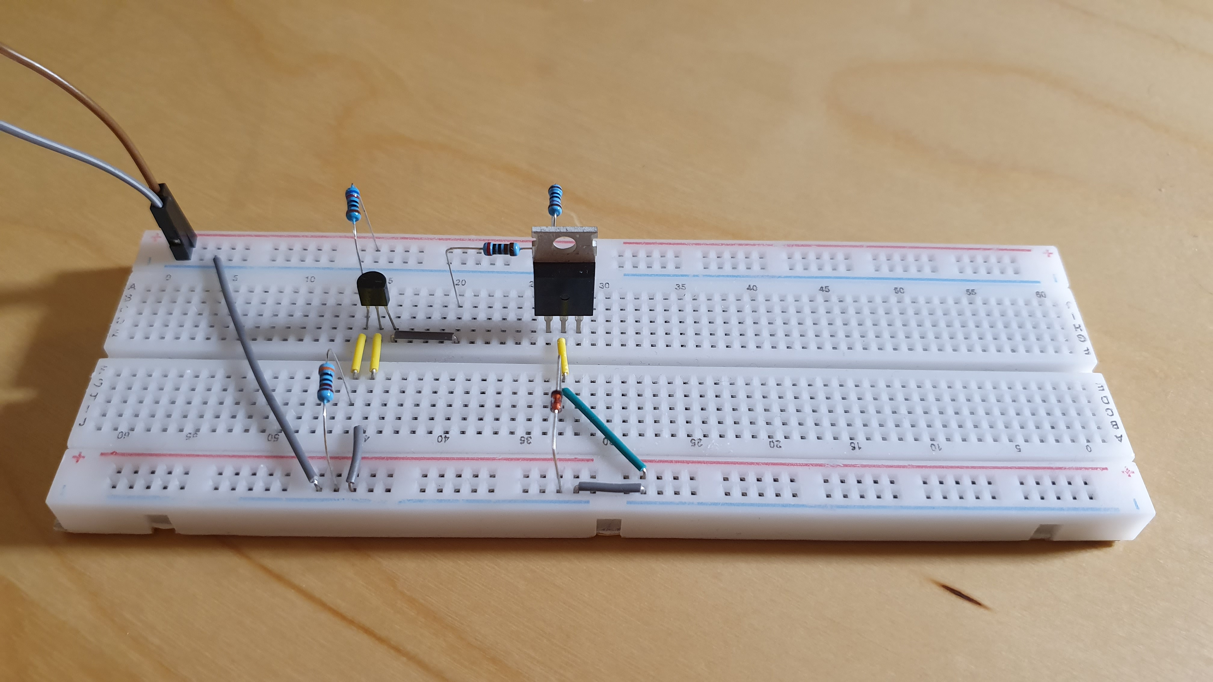
Voltage supervisor circuit with TL431 and a NDP6020 P-Mosfet
The Mosfet is required because the TL431 is only rated for up to 100 mA and the ESP32 needs higher currents when using WLAN. My circuit works, but draws 0.67 mA which is way higher than the deep sleep current. I got the idea for this circuit from a Video3 of the Tech Ideas YouTube Channel.
My next try will be to use a dedicated voltage supervisor. A voltage supervisor that pulls the enable pin of the ESP32 low should disable the ESP32 until the reference voltage of the supervisor circuit is reached.
Once again in a video4 of his YouTube channel, Andreas Spiess explains how they work.
I ordered the one from Texas Instruments and will test it once it arrives.
Efficient engergy harvesting from small voltages
The voltage output of solar panels varies a lot depending on the lighting conditions. With a single 5 V solar panel the voltage output is often lower than the 3.3 V required to power the ESP32. I looked at various power harvesting boards to boost small voltages and store the energy in capacitors but I found none that fullfilled all requirements:
- Start at low voltages (e.g. lower than 2 V)
- Work with 5V or 6V panels
- Store the energy in multiple supercapacitors
- Protect the supercapacitors from overcharing
- Cut off voltage for the Microcontroller (e.g. 3 V)
- Stable power output of 260 mA (ESP32 with WLAN)
Drop me an E-Mail if you have some suggestions.
Current state of the project
I have have a circuit that uses an energy harvester to charge two supercapacitors. Four more supercapacitors store more energy at a higher voltage level before the buck/boost converter of the energy harvester. Solar cells charge the supercaps to a voltage of up to 10 V. The buck/boost converter charges two more supercaps to 3.3 V. All capacitors are protected against overcharging.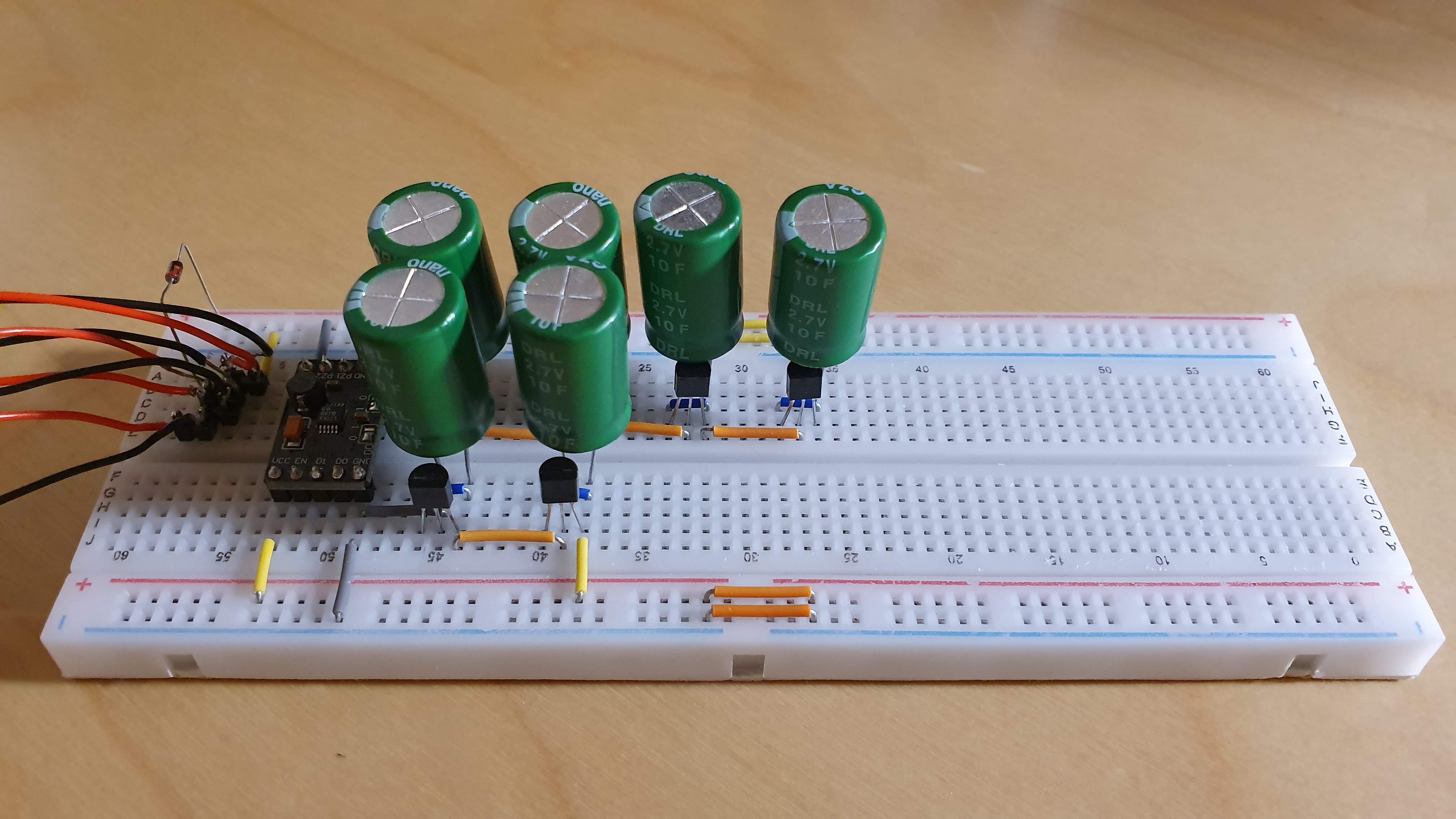
Energy harvester with 3.3 V output and supercapacitors
This is a really bad concept design on breadboard because the capacitors will never be fully charged up to 2.7 V and it also has the problems with undervoltage.
Currently my best idea to solve my problems is to adapt a design5 I found on OpenHardware.io. The design uses a MIC5365-2.7YC5-TR6 to charge capacitors to 2.7 V so I would not have any half charged capacitors. In addition it uses an TPS610986DSET7 (Power Management IC, Current Synchronous Boost, Integrated LDO/Load Switch, 0.7V - 4.5V), which sadly has no undervoltage cutoff for the microcontroller. Therefore my idea is to replace it with a TPS630318 that has the ability to disconnect the load.
So overall: Work in progress. I will update this post when there is some process. If you are willing to help me, please let me know.
Andreas Spiess - Youtube Video - #091 How to properly power the ESP8266 modules ↩︎
Andreas Spiess - Youtube Video - #139 Is there a simple and cheap way to protect your super caps? How? ↩︎
Tech Ideas - Youtube Video - Battery low voltage cutoff circuit | Battery protection circuit ↩︎
Andreas Spiess - Youtube Video - How to use Voltage Supervisors to protect ESP32, Raspberry Pi, and Batteries ↩︎
OpenHardware.io - Super capacitor power supply for wireless sensors with charger ↩︎